I. INTRODUCTION
The introduction of new types of warfare and the rapid development of advanced scientific and military technology have complicated and refined the functions and performance of modern weapon systems. Thus, conventional military support cannot guarantee the effective operation and maintenance of weapon systems [1]. As a result, a number of countries, including the United States, are actively pushing for the implementation of total life-cycle systems management (TLCSM) when acquiring new weapons systems to maximize their operational availability and minimize the total cost of ownership. In particular, it is necessary to minimize equipment downtime and maximize operational availability during its sustainment phase by avoiding unplanned maintenance tasks and ineffective preventive maintenance, reducing maintenance costs through accurate fault detection and time-saving maintenance, and optimizing the spare parts inventory using provision forecasting [2, 3].
In this respect, modern maintenance policies have undergone significant change. Maintenance can be performed using a wide variety of approaches, though the two main categories of maintenance—reactive and proactive—describe the full range of options available. Reactive maintenance is conducted on items that are planned to run to failure or that fail in an unplanned or unscheduled manner and restores the item to a serviceable condition after the failure has occurred. An item may be on a periodic maintenance schedule, but if it fails prematurely, it will require maintenance immediately. Reactive maintenance of a reparable item is thus almost always unscheduled in the sense that the failure was unpredicted. Proactive maintenance is considered either preventive or predictive in nature, ranging from inspections, testing, or servicing to an overhaul or complete replacement. Preventive or scheduled maintenance can be based on calendar time, equipment operation time, or a planned cycle.
Preventive maintenance may be either scheduled or unscheduled. In particular, it can be conducted at a predicted point in time based on the condition of the equipment, the knowledge of which depends on the collection of data associated with potential faults and the deterioration of the equipment [4]. Conventional fault detection methods include built-in tests using in-equipment test algorithms, testing with external test benches, and fault isolation using failure modes, mechanisms, and effects analysis (FMMEA) and fault tree analysis (FTA). However, it is difficult to accurately diagnose faults in time using these strategies. As an alternative, condition-based maintenance (CBM) uses sensors mounted on or within the equipment to measure and analyze its status in real time to predict the remaining useful life (RUL). This allows more effective decisions to be made about when to conduct maintenance and optimizes maintenance plans [5]. Consequently, the system can produce more accurate predictions of impending failure based on the equipment condition data, resulting in dramatic cost-savings and improved weapons-system availability, ultimately benefiting warfare operations [4, 6].
CBM generally consists of five steps, as shown in Fig. 1. In the first step, the necessary data for diagnostics is collected using sensors, thus diagnosing the condition of the equipment and identifying abnormal symptoms. This data is typically collected from elements of the equipment that are easily measured, such as vibrations, noise, temperature, and current/voltage.
In the second step, the data is monitored to determine whether it is normal or not, and a comparative analysis is conducted against baseline data. If a potential fault is detected, the cause of the fault is determined, and it is classified according to the pre-defined severity of its impact on the system.
In the third step, the probability of the fault that has occurred leading to a serious system failure in the future is calculated, and the RUL is predicted. A number of prediction models for RUL have been proposed [2], including data-driven statistical techniques using machine learning, or setting up a physics of failure (PoF) model that matches the characteristics of the equipment.
Step 4 determines the optimal maintenance point based on the estimated RUL and then presents the results to the owners and technicians so that appropriate maintenance tasks can be scheduled and carried out.
As a follow-up, Step 5 optimizes maintenance plans to reflect the CBM results and provides feedback for various logistics concerns, such as the organization of spare parts and maintenance personnel.
A variety of engineering elements are involved in the employment of CBM. This includes hardware, such as embedded sensors used to obtain data and monitor the status of the equipment, and software as part of the decision-making system, including data analysis, the prediction of the RUL based on the failure model, analysis of the cause of failure linked to fault detection, and fault isolation. In addition, the CBM system needs to be underpinned by technical information that encompasses both the information in technical manuals regarding the maintenance of the weapons system in question, and operational information that dictates what maintenance is to be carried out in the event of a failure and how the equipment can be restored following proper procedures. This technical information needs to be organically integrated with the decision-making information deriving from the integrated hardware and software monitoring system, presented in real time, and coupled with diagnostic modules in an interactive electronic technical publication (IETP) based on S1000D, an international specification for technical publications. This CBM information should also interface with the inventory management system to increase the operational availability of the equipment and reduce the total cost of ownership.
S1000D is an international specification for authoring and publishing technical documents that covers the planning, production, management, exchange, and publishing stages. In the 1970s, document standardization was introduced based on the aerospace and defense (ATA-100) specification used by the Air Transport Association (ASD) to resolve the different country-specific document standards that existed in the joint development of European fighter planes, and the S1000D later developed into an international standard. The S1000D utilizes a common source database to support a wide variety of display and publication types by separating the content from the format, allowing authors to focus on the former rather than format editing. It also has the advantage of being able to create a paper manual and an IETP using the same data. An IETP is user-interactive electronic technical publication that presents technical content using digital media and provides search, link, and multimedia functionalities [7]. Chapter 6 in the S1000D specification includes a functionality matrix for IETPs, which includes various diagnostic and prognostic modules that can work with CBM. Table 1 presents data modules (DMs) that contain the diagnostics and prognostics for an IETP and describes each module.
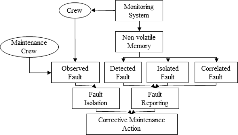
This module is used to carry out fault isolation via pre-defined text references. This employs a sentence format, using “if” phrases to choose an option. It uses a fault schema based on pre-defined FTA to structure fault information and is divided into four types of failure. Fig. 2 presents the four fault types and the troubleshooting procedures presented in the IETP diagnostic module.
This is a decision-making module that utilizes software based on fault-isolation reasoning and logic engines. It provides the user with an appropriate starting point for maintenance to isolate faults and has an external software function.
This involves fault detection or isolation using built-in test (BIT) or separate test devices. It has a direct diagnostic function that isolates fault information from the equipment rather than information entered by the user.
The IETP screen displays diagrams of specific functions and allows the user to select wiring, fluid, and pneumatic-related wiring to track the flow from end to end.
This module displays informal on the normal and abnormal operation of the system and the characteristics of various malfunction types in order to determine or reproduce a fault condition. System simulations allow the user to operate various switches such as those for pressure, valve position, temperature, voltage, and sensor input and make decisions by modeling system operations.
II. MAINTENANCE PLANNING USING CBM
The prediction of the RUL of the equipment using prognostics should be effectively presented to the user. In fact, RUL is variable based on uncertain source data (i.e., that related to performance degradation and future predictions), so it must be expressed to the user quantitatively in real time online for more effective predictive maintenance [8]. Even for the same equipment, RUL may vary depending on the frequency of use and the environment. Therefore, maintenance intervals and policies should be adjusted accordingly. For this purpose, an interlocking concept is required to notify the user of the maintenance timeline and to reflect maintenance information such as maintenance intervals in the maintenance plan in a timely manner through a real-time connection with the IETP described in 1.3. Fig. 3 displays the integration of a pre-set and prognostics-based maintenance schedule into maintenance planning and reducing maintenance costs by reducing the downtime of the equipment.
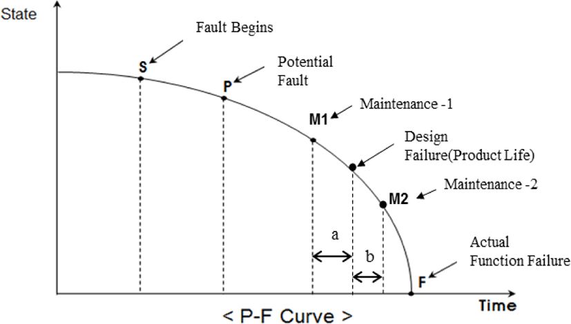
Mechanical equipment that is wearing out or degrading usually shows symptoms of imminent failure before the failure actually occurs. In fact, preventive maintenance in the field is typically performed regardless of the frequency of actual failure [9]. CBM is based on the premise that failures are not immediate, but gradual deterioration with accompanying symptoms. The potential functional P-F curve in Fig. 4 illustrates this process.
The system starts to deteriorate at S, and the potential fault is detected at P with a prognostics algorithm. This does not indicate a functional failure but is rather the point at which the signs associated with the fault begin to be detected. The RUL is predicted from point P to point F, which is the actual function failure. Therefore, the appropriate point for predictive maintenance should be at any point between P and F depending on the degradation condition of the equipment. Most equipment is built with safety margins that allow for longer use than the actual design life, and under these conditions, when maintenance is performed at point M1, which is earlier than the design failure (i.e., the product life), the RUL will not be used as much as ‘a’. This increases the cost of the life cycle. If the maintenance is performed at M2, the equipment can be used for longer than the design life (i.e., period b in Fig. 4) and the cost of the life cycle will be lower. However, the probability of physical failure is dramatically higher, so the cost of downtime and additional costs associated with the actual functional failure must be taken into account.
As the equipment moves closer to actual failure (i.e., it is used longer than the design failure point), more frequent monitoring and preventive maintenance of the equipment can effectively prolong the equipment’s life. On the other hand, the uncertainty of prognostics makes it difficult to set a preventive maintenance point, thus corrective maintenance at the point of failure may be more beneficial from a total cost-of-ownership perspective [10]. Even with the same equipment, the cost and time required for corrective maintenance (i.e., repair) differ from what is required for preventive maintenance (i.e., replacement). Therefore, the point of maintenance and the frequency of M during the overall life cycle of the equipment should be determined by considering availability and the total cost of ownership.
III. OPERATIONAL AVAILABILITY ACCORDING TO THE MAINTENANCE INTERVAL
Several studies have been conducted on how to set maintenance points and intervals based on the RUL predicted by prognostics to minimize the total cost of ownership, but there has been a lack of research on availability [10, 11]. Therefore, this study presents the optimal point of maintenance predicted by prognostics during the total operational period of a weapons system that maximizes operational availability.
In the proposed model, the variables for two systems are set as shown in Table 2 to determine operational availability based on the maintenance interval. The total operating period of System A is 20 years and that of System B is 5 years. The annual operating time is 6,000 hours for both systems, and they both contain electronic equipment with an exponential failure distribution, thus they have the same failure rate. Using Equation (1), this failure rate can be converted to a mean time between failures (MTBF) of 500 hours, which can be used as a reference point for maintenance.
The MTBF can be assumed to be the point of design failure, and if an actual failure occurs at this point, maintenance is performed. The elapsed maintenance time (i.e., the time to repair [TTR]) at this point is longer than the predicted maintenance time (i.e., the time to replacement [TTRM]) because it takes longer to isolate the failure, find the cause of the fault, and to acquire the resources needed to restore the equipment. In addition, maintenance performed in the event of actual failure can also lead to increased downtime for the entire system. Predictive maintenance prior to actual failure usually involves simple replacement tasks and, because no failure has occurred, the effect on the entire system is minor. Therefore, in our model, the elapsed maintenance time and the predicted maintenance time are assumed to be 3 hours and 2 hours, respectively. The cost of maintenance in the event of actual failure should be taken into account not only in terms of the replacement of the item but also in terms of the cost required for further functional checks on the entire system. Therefore, the maintenance costs are assumed to be $300 and $200, respectively.
Operational availability (Ao) can be expressed as a percentage of the total operating period (i.e., uptime + downtime) and system operating time (i.e., uptime only) [12, 13].
Fig. 5 and 6 show the operational availability and maintenance costs of Systems A and B calculated in accordance with Equation (2).
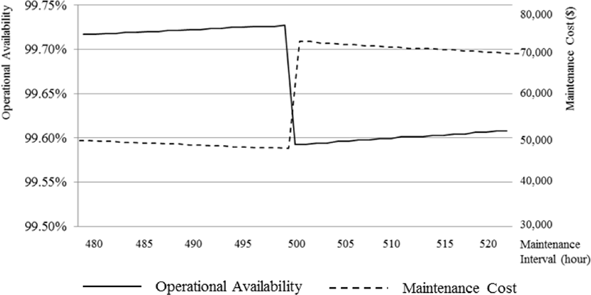
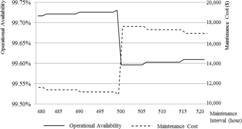
Initially, the longer the maintenance interval, the less frequent the maintenance and downtime of the total operating period, increasing the operational availability. The closer the point of maintenance is to the design failure time (i.e., the MTBF), the greater the RUL. However, because TTR is applied rather than TTRM when the maintenance point passes through the MTBF, the TTR increases rapidly despite the reduction in the number of maintenance tasks, thus the operational availability falls. From that point on, as the maintenance interval increases, the operational availability begins to increase slowly again. Similarly, longer maintenance intervals and fewer tasks reduce maintenance costs but, after MTBF, the total cost of maintenance increases because of the rapid increase in the costs of actual failure. The maintenance costs then begin to decrease again as the number of maintenance tasks decreases. Regardless of the total operating period, Systems A and B both illustrate that the longer the maintenance interval, the greater the operational availability and the lower the maintenance costs.
As Fig. 7 shows, the operational availability of Systems A and B differs as the maintenance interval increases up towards MTBF. When the two systems have the same maintenance interval, System B has a higher operational availability than System A. This means that a system with a shorter total operating period experiences a more beneficial effect in terms of operational availability when maintenance is performed predictably at a time before design failure. It also means that a system with a long operating period requires predictive maintenance at a time as close to design failure as possible to increase its operational availability.
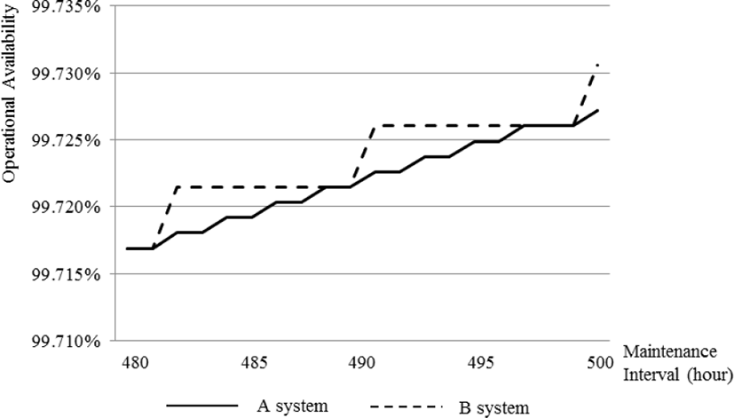
Consequently, while the optimal maintenance point should be determined through prognostics by considering the current state of the system and the operational environment, the total operating period of the system may also be an important factor.
IV. CONCLUSION
In this study, the association between the maintenance interval as determined using prognostics and the operational availability of the system to minimize downtime and cost and maximize operational availability is presented. Two systems with different total operating periods are analyzed for changes in operational availability and maintenance costs with changes in the maintenance interval. It is found that the longer the maintenance interval, the less frequent the maintenance tasks and downtime, and the greater the operational availability. Maintenance costs are also lower because the number of maintenance tasks decreases. More specifically, the operational availability and costs gradually increase and decrease, respectively, before MTBF. They then change drastically at the MTBF, before slowly increasing and decreasing again, respectively, at the same rate. It is also shown that the system with a shorter total operating period experiences a greater benefit from predictive maintenance in terms of increasing operational availability. It is proposed that the maintenance intervals predicted using prognostics and the established maintenance points need to be linked in an IETP based on the international technical publication standard S1000D in order to be effectively presented to users.
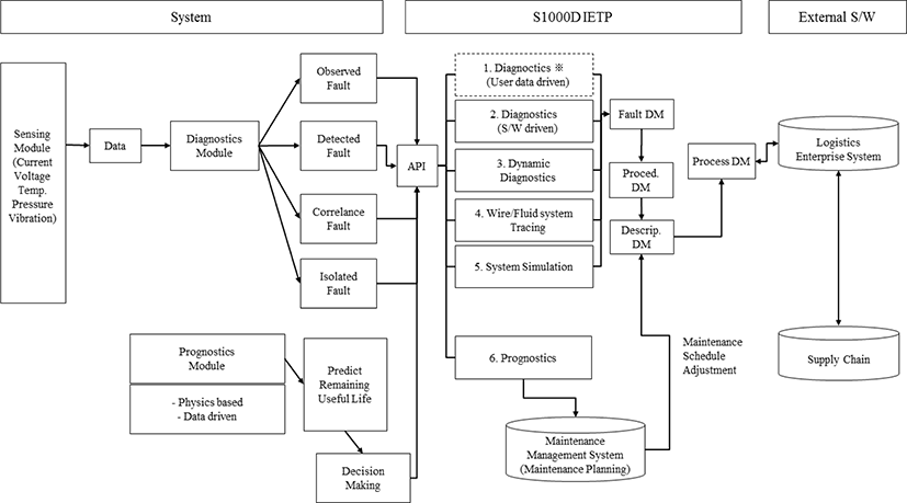
The CBM proposed in this study is summarized in Fig. 8. The CBM sensing module installed in the system is interlinked with the IETP’s diagnostics and prognostics modules, which communicate real-time maintenance-related information to the user. The diagnostics module in the IETP interacts with the process module1 of the previously entered failure isolation procedures through maintenance task analysis and reliability-centered maintenance. The maintenance interval and decisions predicted through prognostics are reflected in the maintenance plan in the description module of the IETP, which is presented in the process module, allowing the user to conduct optimal maintenance.


